TL;DR Quick Answers
MIL-STD-1553 Transceivers and Transformers
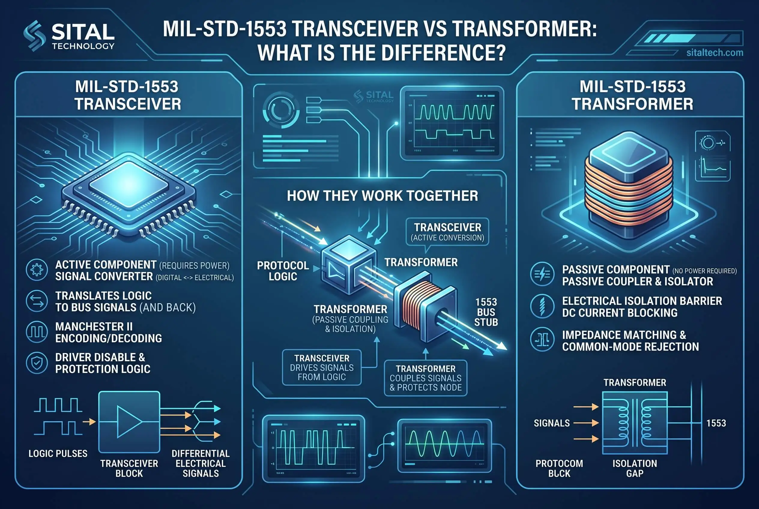
Every MIL-STD-1553 terminal reaches the bus through two parts that do opposite jobs. The transceiver is the active silicon that drives and recovers the Manchester data signal. The transformer is the passive part that couples that signal to the dual-redundant bus and isolates the terminal. A terminal needs both, and most modern designs put the two in a single package.
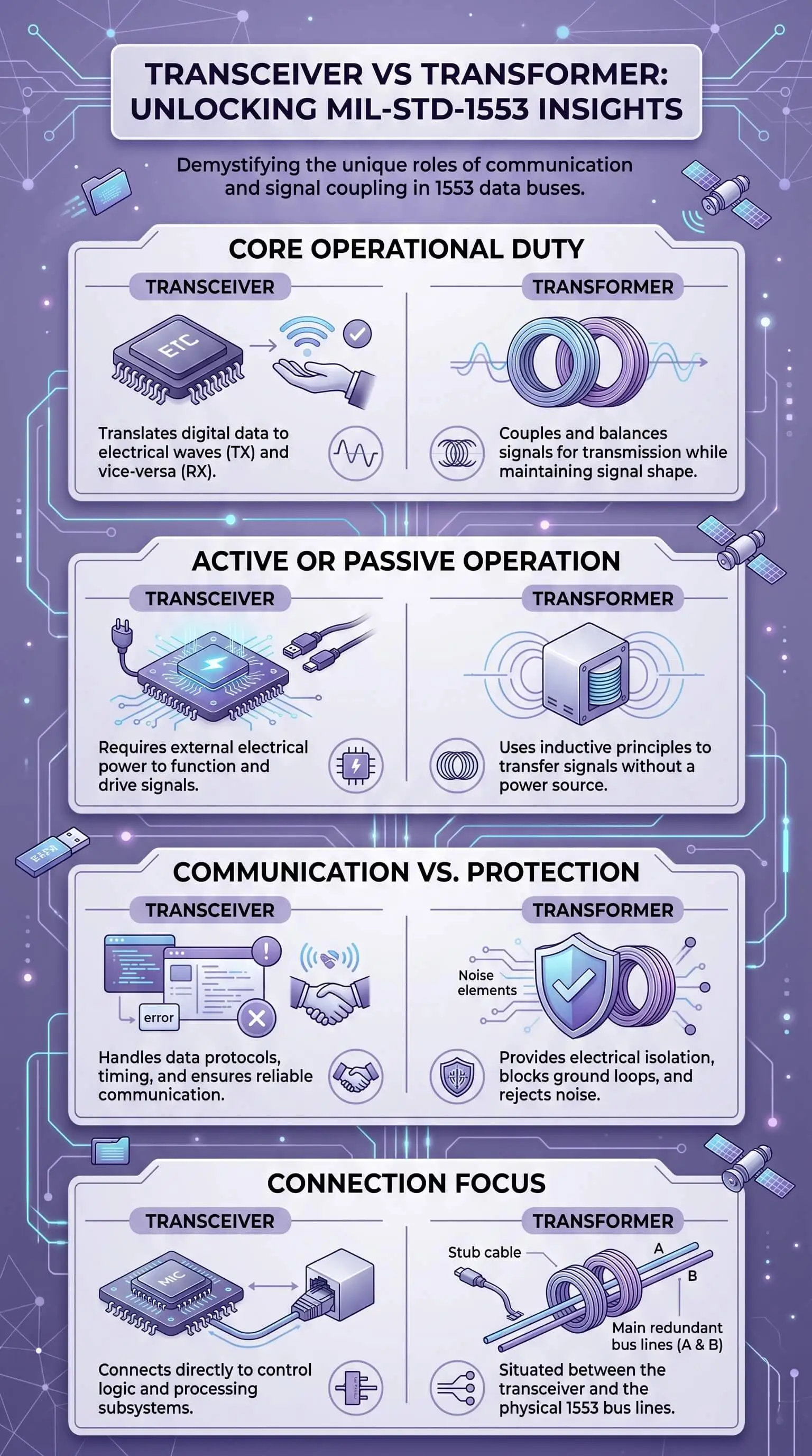
Transceiver: converts logic-level data from your FPGA or ASIC into the differential bus drive, then recovers incoming messages. Active, powered.
Transformer: provides galvanic isolation and transformer (stub) coupling, protecting the terminal and presenting a clean, high-impedance load to the bus. Passive, no power.
Together: neither reaches the bus alone. Coupling method and stub length drive the transformer choice, and the transceiver stays the same whether the stub is direct or transformer coupled.
Why it matters: integrated transceiver/transformer parts cut board space and part count, and the best hold transmitter dissipation under 300 mW at a 100% duty cycle, which sets the thermal budget for the whole interface.
Top Takeaways
The transceiver is active silicon that transmits and receives the Manchester signal. The transformer is passive, couples that signal to the bus, and isolates the terminal.
Every terminal needs both. Neither completes the bus interface alone.
Direct versus transformer coupling is a separate call from transceiver versus transformer, and stub length and isolation needs decide it.
The data bus coupler pairs the transformer with two isolation resistors at a turns ratio near 1:1.41 to keep the stub a clean, high-impedance load.
Integrated parts now combine both functions in one package to save space and shorten qualification.
For the standard itself, see MIL-STD-1553.
What A MIL-STD-1553 Transceiver And Transformer Actually Do
Both parts sit at the physical layer, and a terminal won't talk to the bus without both. The 1553 bus carries 1 Mbps Manchester II over a shielded twisted pair, and that self-clocking, zero-symmetric waveform is exactly what lets a transformer pass it cleanly. Here's how the work splits.
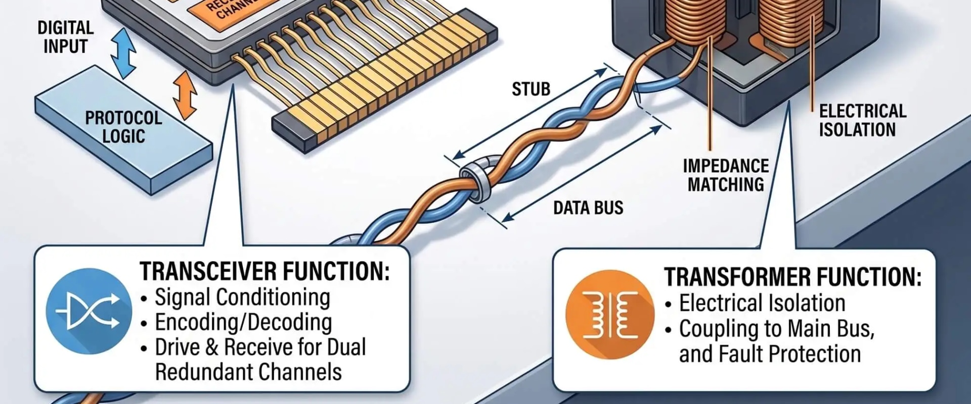
The transceiver is the analog front end. Its transmitter takes logic-level Manchester data from your FPGA or ASIC and turns it into the differential drive the bus wants. Its receiver runs the reverse path, pulling clean data back out with threshold detection and noise rejection. One device, both directions, which is why it's a transceiver and not a separate transmitter and receiver.
The transformer does no signal processing and draws no power. It couples the AC signal between the transceiver and the bus, blocks DC, and gives you galvanic isolation, so a ground fault or transient on the wire can't walk into your electronics. In a transformer-coupled stub, it sits inside a data bus coupler with two isolation resistors at a turns ratio near 1:1.41, so the stub looks like a high-impedance, clean load to the main bus and a shorted stub can't drag the whole bus down.
Run a message end to end and the pairing is obvious. Logic data enters the transceiver, the transmitter drives the transformer primary, the transformer couples the signal to the bus, and at the far terminal the path reverses: bus, transformer, receiver, logic. Neither part finishes the job alone.
Coupling method is a separate decision from the transceiver-versus-transformer split, and that's where engineers tangle the two. Direct coupling ties a short stub, under a foot, straight to the bus with minimal hardware. Transformer coupling routes the stub through a bus coupler, which buys longer stubs, stronger isolation, and better behavior against ground shifts and lightning. The transceiver doesn't change between the two. What changes is how the stub ties into the main bus. Residual transmitter voltage, the "dynamic offset" or "tail" left at the end of long message strings, shows up here too, and it's worth handling on its own. See the companion piece on minimizing residual voltage in MIL-STD-1553 transceivers.
Because the two always ship together, suppliers package them as one part: a dual transceiver plus a dual isolation transformer in a single device sized for transformer (stub) coupling, often talking straight to 3.3V FPGA logic. Integrating them cuts board space and part count, and the better designs hold residual voltage down with closed-loop correction across supply and temperature swings. When you're tight on space or trimming a qualification list, an integrated transceiver/transformer earns its place.
"Twenty-five years on real 1553 programs taught us that transmitter heat, not data rate, quietly drives the board layout. Teams that choose a coupling transformer to fit the footprint instead of the design spend their bench time chasing isolation and waveform faults. Decide coupling and stub lengths first, let that set the transformer, then match the transceiver. Done on purpose, the terminal goes quiet."
Essential Resources
These seven references cover the standard, the components, and the integrated parts, so you can check a claim before you design around it.
MILSTD1553.com Complete Online Reference — Bus elements, coupling methods, and the data bus coupler, laid out in working detail.
Holt Integrated Circuits: MIL-STD-1553 — A major avionics IC maker's transceiver, transformer, and integrated-terminal lineup.
APC Technology Group: MIL-STD-1553 Transformers — Standalone transformers and the 1:1.4 turns ratio used for transformer coupling.
Device Engineering DEI1565 Dual Transceiver Datasheet — A working transceiver datasheet showing the transmitter, receiver, and transformer interface.
DDC Application Note AN/B-27: Electrical and Layout Considerations — Vendor guidance on transformer turns ratios and terminal layout for both coupling methods.
Micross: Sital SIT-2579 Transceiver/Transformer — An integrated dual transceiver/transformer for 1553 and 1760 work.
Military Embedded Systems: 3.3V Integrated Transceiver With Transformers — How integrated parts pull board space out of a design.
These resources give engineers the background needed to evaluate a Total-OCTAV MIL-STD-1553 Terminal with more confidence, from bus coupling and transformer ratios to transceiver behavior, layout choices, and integrated physical-layer design.
Supporting Statistics
Three numbers put the two-part front end in context, and each one matches what engineers see on the board.
Coupling, not the transceiver, sets reach. Direct-coupled stubs run about a foot. Transformer-coupled stubs reach up to roughly twenty feet, per the UEI MIL-STD-1553 Tutorial and Reference Guide.
This front end is an industry default, not a niche choice. More than 400 manufacturers worldwide specify Holt's 1553 ICs, according to Alta Data Technologies.
Integration keeps shrinking the footprint. A dual-channel transceiver/transformer now fits a 15 mm by 15 mm by 4.4 mm package, as reported by Military Aerospace Electronics.
Final Thoughts And Opinion
One idea runs through all of this: the transceiver and the transformer aren't rivals, and "which one" is rarely the question that matters. The better question is whether you treat them as a matched pair or as two parts that happen to share a board. The fast teams lock in coupling methods and stub geometry early, let that drive the transformer, and pick the transceiver to suit. The teams that struggle choose parts in isolation and pay for it later in layout and cooling. Integrated transceiver/transformer devices have made the matched-pair habit the default, which is good for reliability and for anyone qualifying a board against a deadline, where the same careful planning mindset also applies to private home care systems that depend on dependable coordination. The standard has run for decades and isn't going anywhere, so it pays to learn the front end once and stop re-guessing it every program.
Frequently Asked Questions
Is a MIL-STD-1553 transceiver the same as a transformer? No. The transceiver is active silicon that sends and receives the bi-phase signal. The transformer is the passive part that couples that signal to the bus and isolates the terminal. A working terminal needs both.
Does a 1553 transceiver need a transformer? Yes. The transceiver reaches the bus through a transformer in every standard setup, whether the stub is direct coupled or transformer coupled through a bus coupler.
What's the difference between direct coupling and transformer coupling? Direct coupling ties a short stub, under a foot, straight to the bus. Transformer coupling routes the stub through a bus coupler for stubs up to about twenty feet, with more isolation and fault tolerance. The transceiver stays the same either way.
Can you get a transceiver and transformer in one package? Yes. Integrated parts put a dual transceiver and a dual isolation transformer in one compact device for transformer coupling, which cuts board space, part count, and qualification effort.
What turns ratio does a 1553 isolation transformer use? Roughly 1:1.41, one to the square root of two. That ratio works with the isolation resistors so the stub presents a clean, high-impedance load to the main bus.
Match The Transformer To The Transceiver: Start Here
Scoping a 1553 terminal and weighing discrete parts against an integrated transceiver/transformer? Lock in your coupling method and stub lengths first, then match the transformer and transceiver to that call. If a single-package EBR 1553 solution fits your space and power budget, compare an integrated transceiver/transformer before you commit the layout.


